### Version 4.3.1 Stable
* Fix and clear code.
### Version 4.3.09_dev
* Add Save in EEPROM ABL (Linear or Bilinear) or MBL
* Add M323 Set Level bilinear manual – X Y Z S
* Add Door open, a triggered door will prevent new commands from serial or sd card.
* Fix HAL
### Version 4.3.08_dev
* Add ABL or MBL leveling fade height M320 Z (ABL) or M420 Z (MBL)
* Add RGB LED M150: Set Status LED Color – Use R-U-B for R-G-B
* Add Case Light M355 S P
* Add M995 X Y Z set origin for graphic in NEXTION
* Add M996 S scale graphic in NEXTION
* Add Autocalibration 7 points for DELTA (Similar RepRapFirmware)
### Version 4.3.07_dev
* Add ENSURE_SMOOTH_MOVES – Enable this option to prevent the machine from stuttering when printing multiple short segments.
* Add USE_BIG_EDIT_FONT – A bigger font is available for edit items in graphical displays. Costs 3120 bytes of PROGMEM.
* Add USE_SMALL_INFOFONT – A smaller font may be used on the Info Screen in graphical displays. Costs 2300 bytes of PROGMEM.
* Add Waveform temperature for Nextion.
* Add option for refresh Nextion
* Add option for name firmware file Nextion
### Version 4.3.06_dev
* Add Auto report temp width M155
* Add new capabilities string width M115
* Add M155 Set temperature auto-report interval
* Add M320 Activate autolevel
* Add M321 Deactivate autoleveling
* Add M322 Reset auto leveling matrix
* Change M11 in M530
* Add M530 Enables explicit printing mode (S1) or disables it (S0). L can set layer count
* Add M531 Define filename being printed
* Add M532 update current print state progress (X=0..100) and layer L
### Version 4.3.05_dev
* Add register in EEPROM Bilinear Bed Level
* Add M355 Turn case lights on/off
* Fix Error width 8bit and 2 or more Hotends
* Upgrade Nextion width Filament Change
* New Fix
### Version 4.3.04_dev
* Fix Code
* Fix JERK
* Fix Save Stop Restart
* Update Nextion Graphic made Mr. Goblins
* Add M43 Pins test and debugs
### Version 4.3.03_dev
* Clear Code
* ABL revision (ABL 3 point, ABL Linear, ABL Bilinear)
### Version 4.3.02_dev
* Clear code
* Add Fast inverse sqrt from Quake III Arena see https://en.wikipedia.org/wiki/Fast_inverse_square_root
### Version 4.3.01_dev
* Add Nozzle Clean Feature
* Add Nozzle Park Feature
### Version 4.3.0_dev
* New MK4duo, only version for Arduino and Arduino due
### Versin 4.2.9
* Last version for only 32 bit
### Version 4.2.89
* Fix and clear code
* Add X dual motor
* Add custom bootscreen
### Version 4.2.88
* Fix and clear code
* Rewrite communication
### Version 4.2.87
* Fix and clear code
### Version 4.2.86
* Fix Type probe
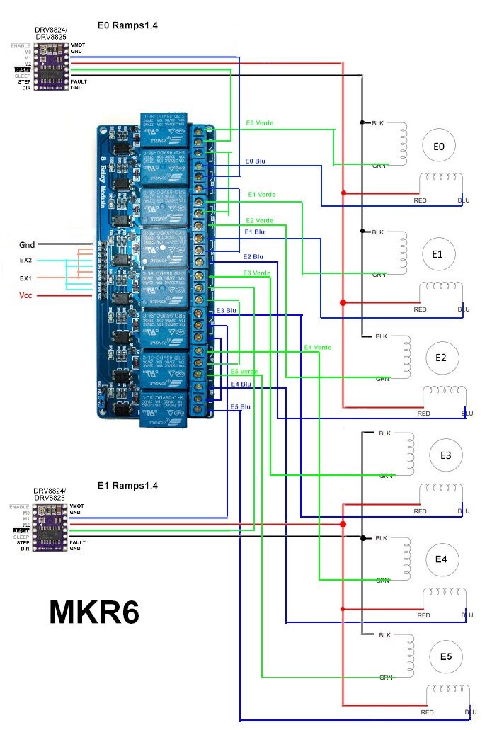
* Add MKR6 system
* Fix and clear code
### Version 4.2.85
* Add Stop and Save for Restart (SSR)
### Version 4.2.84
* Add Mesh Bed Level (MBL)
### Version 4.2.83
* Add Cooler and Hot Chamber
* Add Laser Beam PWM and raster base64
### Version 4.2.82
* Add DONDOLO_DUAL_MOTOR for DONDOLO bowden and dual extruder
* Add reader TAG width MFRC522
### Version 4.2.81
* Fix serial protocol for Repetier Host
* Bug fix
### Version 4.2.8
* Add board folder with files of various board containing the pins
* Add End time on Graphics display when SD print
* Add M35 for upload firmware to Nextion from SD
* Rewrite macros
* Fix M109 so it won’t wait for cooling
* Clear code
* Bug fix
### Version 4.2.7
* Add M906 Set motor Currents for ALLIGATOR board
* Add M408 JSON OUTPUT
* Add Cartesian Correction Hysteresis and Zwooble
* Bug fix
### Version 4.2.6
* Bug Fix
### Version 4.2.5
* Big Update
* Add HAL for 8 bit version
* Rewrite Communication
* Rewrite Servo
* Add Color Mixing Extruder
### Version 4.2.4
* Added Abort on endstop hit feature
* Added Purge command G1 P
* Added M222 T S set density extrude factor percentage for purge
### Version 4.2.3
* Added Filament tot printed in stats
* Overall rewrite
### Version 4.2.2
* Added the possibility to invert the logic for lcd buttons.
* Language files bugfix.
* Fixed a freeze problem during write operations to the SD.
* Re-enabled by default SDSUPPORT for DISCOUNT displays.
### Version 4.2.1
* SDSUPPORT disabled by default.
* General BugFix.
### Version 4.2.0
* Add Dual Extruder DONDOLO.
* Add PID Extrusion Rate Kc in percent.
* New configuration systems (Now you can create a separate file with all configuration and use it in you FW update).
* New namings for file.
* Added more documentation inside configuration file.
* More checks for feature incompatibility during compilation.
* Codeclean.
* General bugfix.
* Removed legacy support for old configuration (Do not use your old configuration files, namings and position for configuration has changed).
### Version 4.1.5
* Added dot for SD write operation.
* Added statistics menu.
* Added an overall configuration file.
* Added M70 gcode for calibrate AC721 current sensor.
* Added documentation for calibrate AC721 current sensor.
* Critical stepper motor frequency bugfix.
* Introduced more intuitive menu tree.
* Added a menu option to fix loose steps from LCD.
* Improved italian translation.
* G28 gcode now support the “B” flag that enable you to come back to the last position of the axis before the homing command. (Used for fix loose steps)
* Implemented FAST_PWM_FAN and FAN_SOFT_PWM also for other fan that can be added in configuration_adv file.
* Added the ability to set a min speed to the fan that can be added in configuration_adv file.
* General bugfix.
### Version 4.1.4
* Add support for Piggy Alligator board
* Add Debug_info. Repetier button info for enabled or disabled, or M111 S2 for enabled and M111 S0 for disabled.
* Improved Topography Auto Bed Level.
* Add Dryrun ABL and verbose width command G29 D or G29 V(0-4).
* Improve Autoconfiguration for Delta printer.
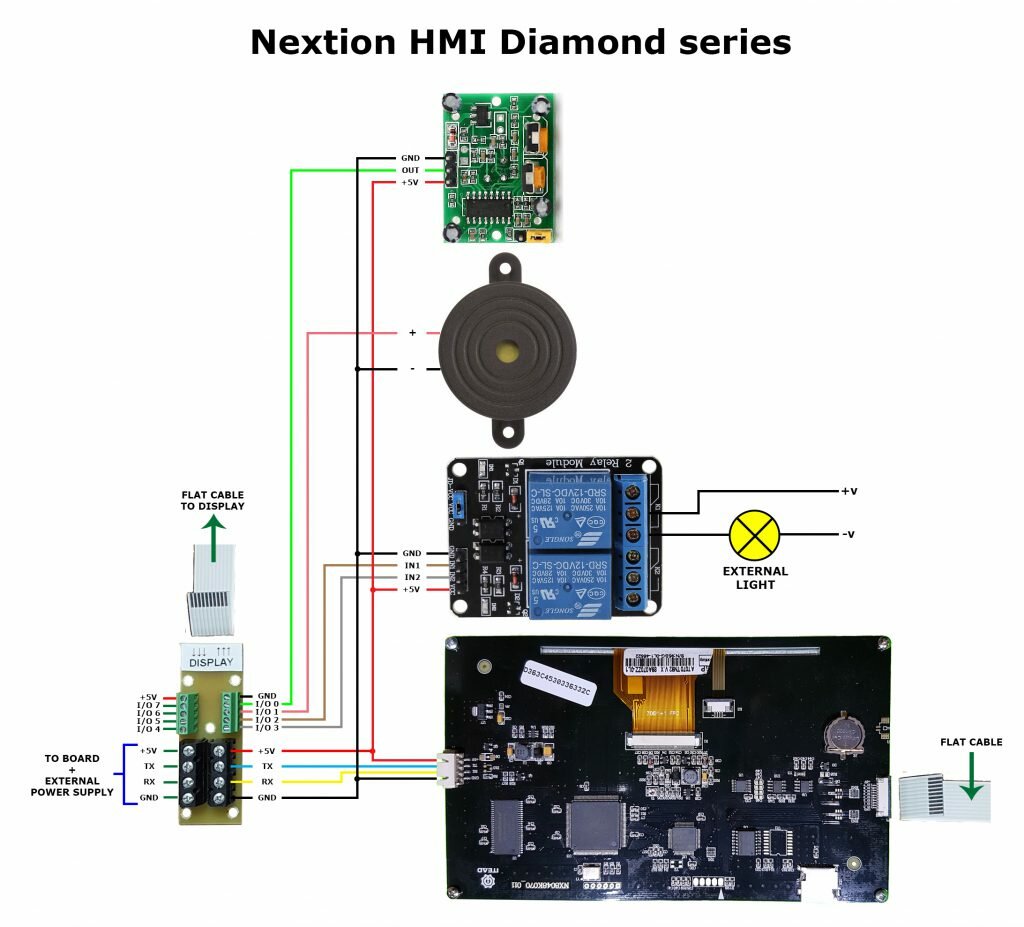
* Add support (test only) for NEXTION HMI LCD.
* Improved firmare test dialog.
* Bugfix for SDCONFIG routine. Now the configuration file will be readed and created only on the root of the SD.
* Improved “Thermal Runaway Protection” now the system will be halted also if the thermistor is missing before the temperature is reached as suggested in Issue #35.
* Improved “Extruder Idle Oozing Prevention” by adding a more efficient way to detect planned movements. Now this feature seems stable and can be used by anyone.
* Bugfix for sdinit.
* Removed tab character from the code.
* Removed some unuseful spacing from the code.
### Version 4.1.3
* Improved support for Delta, SCARA, COREXY & COREXZ kinematics.
* Improved stepper timer for high velocity driver and not.
* Add calibrate surface width DELTA.
* Improved serial comunication width most popular Host.
* Add Acceleration retraction for extruder.
* Add EJerk for extruder.
* Remove limit for virtual extruder to 4. Now width MKR4 or NPr2 is possible have infinite extruder…
* Add M92 T* E (Set step per unit for any extruder).
* Add M203 T* E (Set max feedrate for any extruder).
* Add M204 T* R (Set acc retraction for any extruder).
* Add M205 T* E (Set E Jerk for any extruder).
* Add Slot for G60 & G61.
* G60 Save current position coordinates (all axes, for active extruder). S – specifies memory slot # (0-based) to save into (default 0).
* G61 Apply/restore saved coordinates to the active extruder. X Y Z E – Value to add at stored coordinates. F – Set Feedrate. S – specifies memory slot # (0-based) to save into (default 0).
### Version 4.1.2
* Serial message function standardized for a better code style.
* Auto-Create configuration file if not exist.
* FIX for sdcard crash problem during configuration file reading.
* FIX for some undefined SCARA defines.
### Version 4.1.1
* Added Power (Watt) Sensor.
* Added Anti OOZING.
* Add Power Consumation and Power On Time.
* Configurations stored in the SD are updated in real-time (every SD_CFG_SECONDS seconds) also if you remove-insert the sd or you start your printer without the SD card.
* Reduced code size, maybe a lot depending on your configuration.
* Improved support for Delta, SCARA, and COREXY kinematics.
* Move parts of Configuration files to `Conditionals.h` and `SanityCheck.h`.
* Clean up of temperature code.
* Enhanced `G29` with improved grid bed leveling based on Roxy code. See documentation.
* EEPROM layout updated to `V21`.
* Added `M204` travel acceleration options.
* `M204` “`P`” parameter replaces “`S`.” “`S`” retained for backward compatibility.
* `M404` “`N`” parameter replaced with “`W`.” (“`N`” is for line numbers only).
* Much cleanup of the code.
* Improved support for Cyrillic and accented languages.
* LCD controller knob acceleration.
* Improved compatibility with various sensors, MAX6675 thermocouple.
* Filament runout sensor support.
* Filament width measurement support.
* Support for TMC and L6470 stepper drivers.
* Better support of G-Code `;` comments, `\`, `N` line numbers, and `*` checksums.
* Moved GCode handling code into individual functions per-code.
### Version 4.1.0
* Initial release.


![SainSmart-8-Channel-DC-5V-Relay-01[1]](/wp-content/uploads/2016/03/SainSmart-8-Channel-DC-5V-Relay-011-300x174.jpg)

